VYCON Technology
The proprietary components of the VYCON flywheel provide a number of distinct advantages, including:
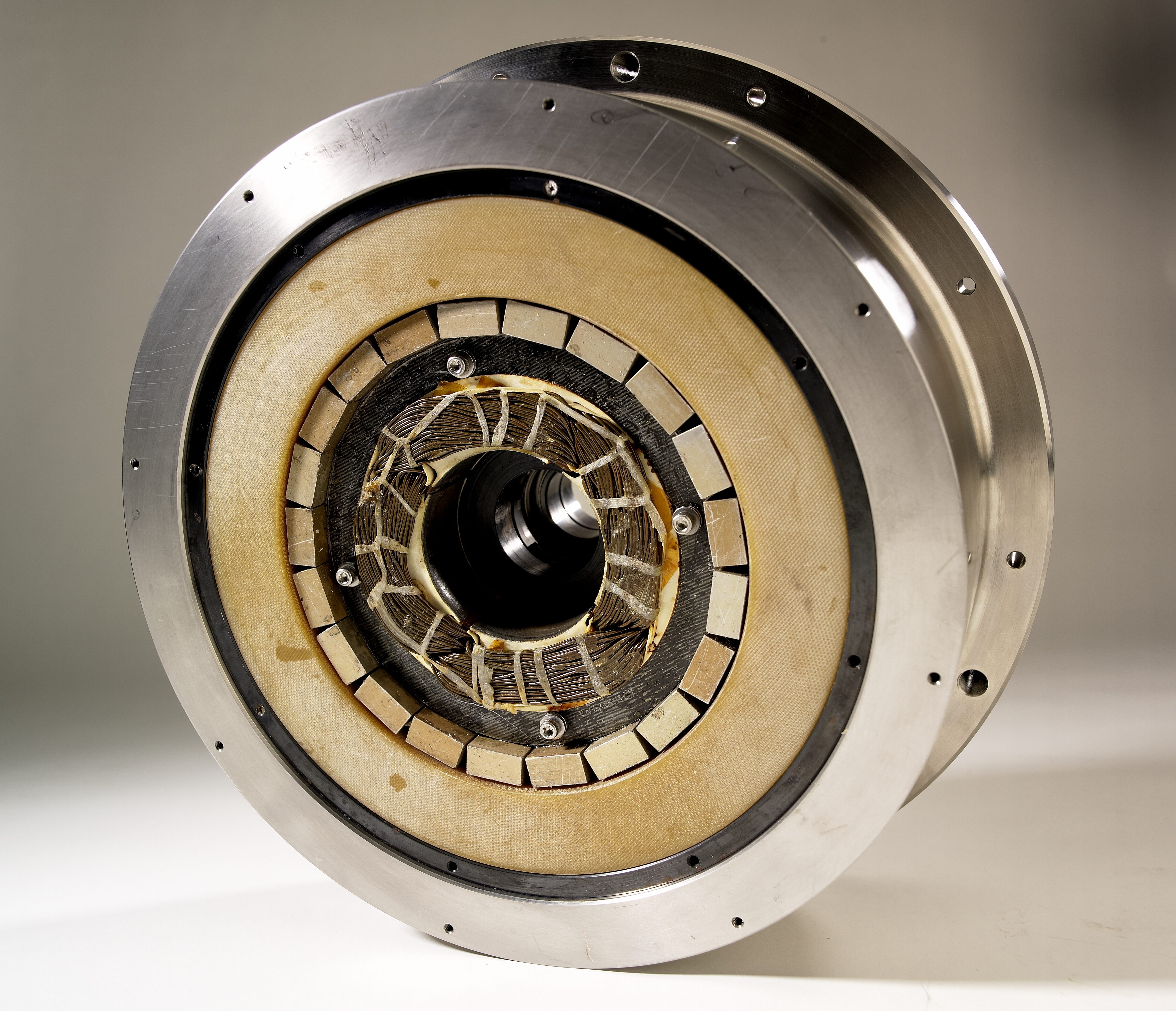
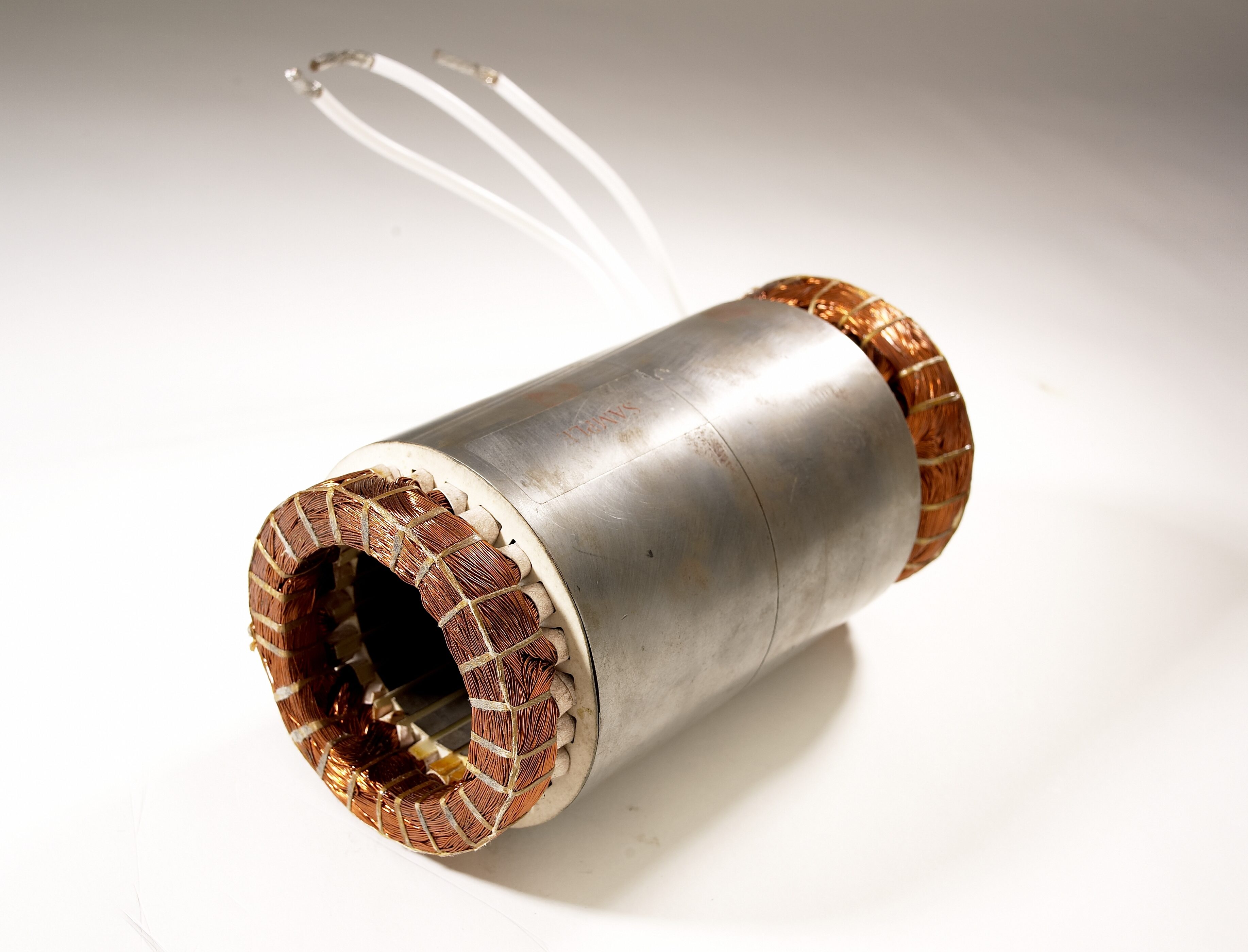
High-Speed Permanent Magnet Motor Generator
The VDC systems’ motor generator design utilizes specialized rare earth magnets to minimize rotor heating and maximize efficiency and reliability. This type of motor design allows the system to cycle quickly without overheating and can, therefore, be used in difficult applications with high cycling and long life requirements. The motor generator is rotated at speeds up to 36,750 RPM, where the flywheel system is at a fully charged state. During discharge, the rotor speed decreases to a minimum speed, typically 10,000-12,000 RPM. This speed range is called the discharge range and can be adjusted for more energy or higher cycling depending on the application. The rotor assembly of the flywheel operates in a vacuum provided by an external pump. By removing air from the rotating area of the motor, all windage losses from the system are eliminated, increasing electrical efficiency.
Magnetic Bearings and Controls
Magnetic bearings allow the motor assembly to rotate at very high speeds with no physical contact to stationary components, thereby taking advantage of the high efficiencies obtainable with high-speed rotation.
Magnetic bearings levitate the rotating assembly through the force of a magnetic field, and the upper and lower magnetic bearings provide five axes of support, which include the axial and radial support. The VYCON magnetic bearing design is based on a combination of permanent magnets, which provides a bias field in the gap, and controlled electromagnets, which provide the adjustment and centering of the rotor assembly. To minimize bearing power requirements and losses, the flywheel is vertically oriented, thereby only requiring the axial bearing axes to support the full rotor weight. The position of the rotor assembly is controlled by the magnetic bearing controller (MBC), which feeds rotor position information from position sensors next to the magnetic bearing actuator.
The MBC contains a digital controller, sensor inputs and current amplifiers that monitor and control the position of the flywheel rotor via a five-axes active magnetic bearing system. The controller in turn adjusts the current into each coil to reposition the rotor within an allowable orbit. The rotor position signals are fed to the control module, which runs a digital filter compensation program to produce a command signal for each current amplifier. The current amplifiers provide the drive current to the actuators of each axis, thereby applying the forces on the rotor that maintains the desired flywheel rotor position.
The patented magnetic bearing technology eliminates virtually all maintenance, including the need to replace or repack lubricant for a mechanical bearing system. As a result, VDC energy storage systems have a 20-year life with no bearing maintenance.
Bi-Directional Power Converter
The power module is an Insulated Gate Bipolar Transistor based bi-directional direct current (DC) to alternating current (AC) or AC to DC device. During the charging or motoring state, it acts like Uninterruptible Power Source (UPS) inverter, and the power module converts DC from the UPS to 3-phase AC that is applied to the stator and spins the flywheel. While it is discharging or generating, it acts like a UPS rectifier; the power module converts the 3-phase AC from the flywheel motor-generator to a regulated DC.
Smart Monitoring System
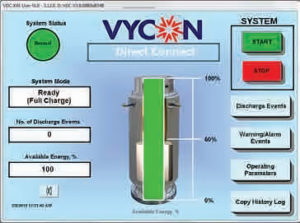 VDC energy storage systems feature a user-friendly touchscreen interface as the primary means for the operator to monitor and control the system. The touchscreen interface displays an assortment of information, including system information, system status, system errors, operating parameters and event log menus. The control panel is designed to provide the user with a graphical description of the flywheel storage in real time. The screen provides rotor speed, change capacity, discharge event history, adjustable voltage –settings, RS-232/485 interface, alarm status contacts, soft-start pre-charge from DC bus and push-button shutdown. The “Service GUI” contains the interface for multiple trouble-shooting, calibration and set-up capabilities.
Reduce Costs & Increase Backup Reliability
- 20x higher reliability over VRLA batteries
- Environmentally friendly/low carbon footprint
- 20-year operational life
- High power density
- Operate in high temperature environments
- No bearings to replace